|
Ningbo Vichnet Communication Science & Technology Ltd.
|
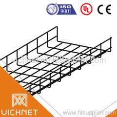
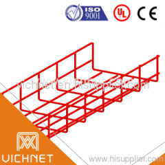
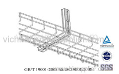
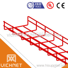
wire mesh cable
| Price: | 5.0~50.0 USD |
| Payment Terms: | T/T,L/C |
| Place of Origin: | Zhejiang, China (Mainland) |
|
|
|
| Add to My Favorites | |
| HiSupplier Escrow |
Product Detail
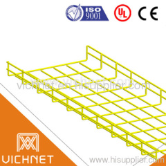
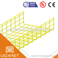
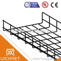
1.Focus on producing Wire Grid Cable Tray
2.ISO9001:2008/UL/CUL/CE,passed Rohs test
3.Wire Grid Cable Tray EZ>12u ,HDG>60u
Brief Introduction of Cable Tray Systems:
A cable tray system, according to the US National Electrical Code, is "a unit or assembly of units or sections and associated fittings forming a rigid structural system used to securely fasten or support cables and raceways." Cable trays are used to hold up and distribute cables.
Cable trays are widely used as temporary usage of electric power in building site, industry and mining enterprise, decoration and mending where adopt the electric power of 220V and 380V.
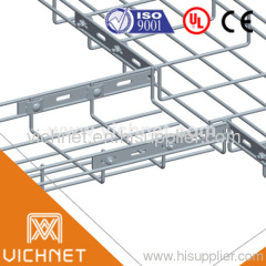
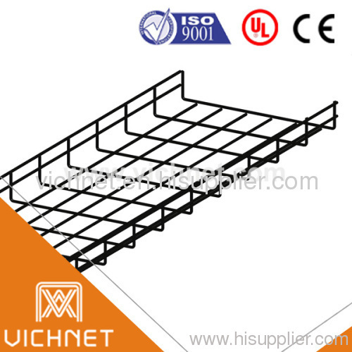
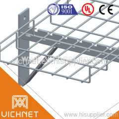
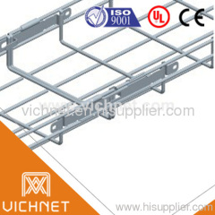
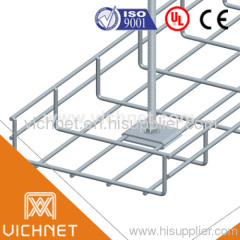
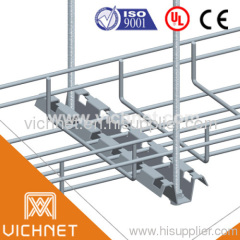
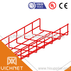
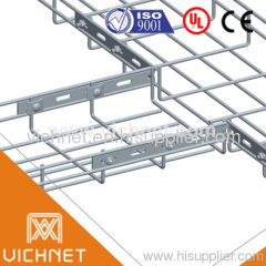
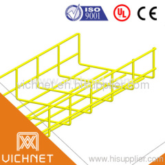
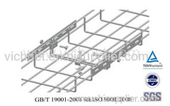
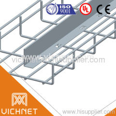
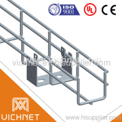
Wire mesh cable trays are used extensively for data cables and low voltage installations, steel wire tray has become increasingly popular with installers thanks to its ease of use, flexibility and lightweight structure. They are appropriate for Sensitive cables such as control cables, optical cables, telecommunication cables, etc.
The Installation time of mesh trays is reduced and no expensive preformed fittings have to be specially planned for or ordered. Fast, simple shaping can be carried out entirely on site. A bolt cutter, screw driver and a wrench are the only tools required to create the most complex of cable runs. A wide range of unique supports improves installation time even more. The tray is so easy to manipulate, one person can install a system unaided.
Features and Benefits of Wire Mesh Cable Trays:
1. Low cost.
2. Light in weight.
3. Easy for line check and cleaning.
4. Easy maintained.
5. Fast heat dispersion.
6. Cables can be secured to clamps or ties.
7. Flexible and fast installation.
8. Safe-T-Edge design to protect cables.
2. Light in weight.
3. Easy for line check and cleaning.
4. Easy maintained.
5. Fast heat dispersion.
6. Cables can be secured to clamps or ties.
7. Flexible and fast installation.
8. Safe-T-Edge design to protect cables.
9. Strong enough to withstand short circuits.
Manufacturing:
Optional Material: Black Steel, Stainless Steel, Aluminium, Alloy, Fibreglass Reinforced Plastic (FRP)
Mode: Top curved / Top Straight
Surface Finish: Zinc-plating, Hot-dip Galvanizing (HDG), Powder-coated, Pickled & Passivated.
Color: Optional
We are able to design styles in various specifications according to the drawings and/or samples by the clients.
Suggestions:
1). MATERIAL
The choice of materials is a matter of the physical and mechanical properties produced by each, compared against the intended function, as well as the environment, in which the trays are to be installed.
2). SURFACE FINISH:
A). Zinc-plating cable trays are suitable for indoor use. The place where cold zinc-plating cable trays would work should be dry, ventilated, and corrosion free.
B). Hot-dip Galvanizing (HDG) cable trays are suitable for outdoor use. They should be used in a place where there is no acid, alkali and salty substance in case of short working life.
C). Powder-coated cable trays should be carried out in alkali and salt corrosion free site.
D). Pickled & Passivated should be used to stainless steel wire trays.
Specification for power and communications cabling containment.
1). SCOPE
Steel Wire Cable Tray conforming to the material and performance of this specification.
2). GENERAL
A). Cable tray shall be manufactured from steel wires, welded together and bent into final shape prior to surface treatment.
B). Surface Treatments:
i). Electro zinc plated to BSEN 12329-2000 for interior use (level 2)
ii). Hot Dipped Galvanised with between 60 and 80 microns of zinc to BS 729.
iii). Stainless Steel AFNOREZ CND 17.2 (AISI 316L)
C). Steel Wire Cable Tray Widths & Depths
i). Cable Tray dimensions are all internal.
ii). Depths of 30mm, 54mm, 80mm, 105mm & 150mm
iii). Widths of 50mm, 100mm, 150mm, 200mm, 300mm, 400mm 450mm, 500mm & 600mm for depths of 30mm & 54mm.
iv). Widths of 100mm, 150mm, 200mm, 300mm 400mm & 500mm for Depths of 105mm & 150mm
All trays are of 3005mm long
3). SPECIFICATION
a). Steel Wire Cable Tray will be produced from lateral and longitudinal sidewall steel wires, with minimum diameters of -:
4 mm for trays of widths up to 150mm
4.5 mm for trays of widths of 200mm
5.0 mm for trays of widths of 300mm
6.0 mm for trays of widths of 400mm, 450mm, 500mm and 600mm
b). Trays will be manufactured with a longitudinal 'T-welded' safety edge along the top wire of the sidewall (excluding CF3050)
c). Trays will be constructed with a 50mm x 100mm mesh configuration.
d). All tray fittings (e.g. changes in direction, level and size) shall be constructed on site, to the manufacturers instructions, using side action bolt croppers and fastened using 25mm and 30mm counter clamps with M6 bolts and nuts, all surface treated as the tray.
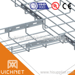
e). Trays will be coupled together using either a fast spring coupler or a 25mm/30mm counter clamp combination with supporting lateral splice plate on trays over 300mm width. The coupling will have the same surface finish as the tray.
f). Trays shall be supported at a maximum span of 2.5m by trapeze, wall, floor or channel mounting methods and will not exceed maximum loads as specified by the manufacturer.
g). All welds will be manufactured to an average minimum tensile strength of 500Kg per weld.
4. TESTS, CERTIFICATION AND CONFORMITY
a). Loading and deflection characteristics of the tray should be tested and the results published in accordance with the European Standard CEI/61537.
b). Suitability for the support of Cat6 data cabling should be demonstrated by way of independent test verification.
c). Fire test certification should be published in accordance with the E30/E90 standard.
d). Electrical continuity across a coupling should be demonstrated by means of a published test method and result.
Didn't find what you're looking for?
Post Buying Lead or contact
HiSupplier Customer Service Center
for help!
Related Search
Wire Mesh Cable Tray
Cable Wire Mesh
Wire Cable
Mesh Cable Tray
Electrical Wire And Cable
Car Wire Cable
More>>

.jpg)
.jpg)
.jpg)
.jpg)
.jpg)
.jpg)
